Quantcast
Channel: JetsonHacks
Viewing all 339 articles
Browse latest View live

Robot Operating System (ROS) on NVIDIA Jetson AGX Xavier Developer Kit

$
0
0

For robotics application, one of the leading set of tools is Robot Operating System (ROS). The version of ROS that runs on the Jetson AGX Xavier is ROS Melodic. Installing ROS on the Jetson Xavier is simple. Looky here:

Background

ROS was originally developed at Stanford University as a platform to integrate methods drawn from all areas of artificial intelligence, including machine learning, vision, navigation, planning, reasoning, and speech/natural language processing.

From 2008 until 2013, development on ROS was performed primarily at the robotics research company Willow Garage who open sourced the code. During that time, researchers at over 20 different institutions collaborated with Willow Garage and contributed to the code base. In 2013, ROS stewardship transitioned to the Open Source Robotics Foundation.

From the ROS website:

The Robot Operating System (ROS) is a flexible framework for writing robot software. It is a collection of tools, libraries, and conventions that aim to simplify the task of creating complex and robust robot behavior across a wide variety of robotic platforms.

Why? Because creating truly robust, general-purpose robot software is hard. From the robot’s perspective, problems that seem trivial to humans often vary wildly between instances of tasks and environments. Dealing with these variations is so hard that no single individual, laboratory, or institution can hope to do it on their own.

Core Components

At the lowest level, ROS offers a message passing interface that provides inter-process communication. Like most message passing systems, ROS has a publish/subscribe mechanism along with request/response procedure calls. An important thing to remember about ROS, and one of the reason that it is so powerful, is that you can run the system on a heterogeneous group of computers. This allows you to distribute tasks across different systems easily.

For example, you may want to have the Jetson running as the main node, and controlling other processors as control subsystems. A concrete example is to have the Jetson doing a high level task like path planning, and instructing micro controllers to perform lower level tasks like controlling motors to drive the robot to a goal.

At a higher level, ROS provides facilities and tools for a Robot Description Language, diagnostics, pose estimation, localization, navigation and visualization.

You can read more about the Core Components here.

Installation

There is a repository on the JetsonHacks account on Github named installROSXavier.
The main script, installROS.sh, is a straightforward implementation of the install instructions taken from the ROS Wiki. The instructions install ROS Melodic on the Jetson Xavier.

You can clone the repository on the Jetson:

$ git clone https://github.com/jetsonhacks/installROSXavier.git
$ cd installROSXavier

installROS.sh

The install script installROS.sh will install the prerequisites and ROS packages specified. Usage:

Usage: ./installROS.sh  [[-p package] | [-h]]
 -p | --package <packagename>  ROS package to install
                               Multiple Usage allowed
                               The first package should be a base package. One of the following:
                                 ros-melodic-ros-base
                                 ros-melodic-desktop
                                 ros-melodic-desktop-full
 

Default is ros-melodic-ros-base if no packages are specified.

Example Usage:

$ ./installROS.sh -p ros-melodic-desktop -p ros-melodic-rgbd-launch

This script installs a baseline ROS environment. There are several tasks:

  • Enable repositories universe, multiverse, and restricted
  • Adds the ROS sources list
  • Sets the needed keys
  • Loads specified ROS packages (defaults to ros-melodic-base-ros if none specified)
  • Initializes rosdep

You can edit this file to add the ROS packages for your application.

setupCatkinWorkspace.sh

setupCatkinWorkspace.sh builds a Catkin Workspace.

Usage:

$ ./setupCatkinWorkspace.sh [optionalWorkspaceName]

where optionalWorkspaceName is the name and path of the workspace to be used. The default workspace name is catkin_ws. If a path is not specified, the default path is the current home directory. This script also sets up some ROS environment variables.

The script sets placeholders for some ROS environment variables in the file .bashrc
.bashrc is located in the home directory. The names of the variables are (they should be towards the bottom of the .bashrc file):

  • ROS_MASTER_URI
  • ROS_IP

The script sets ROS_MASTER_URI to the local host, and basically lists the network interfaces after the ROS_IP entry. You will need to configure these variables for your robots network configuration. Refer to the script for further details.

Notes

  • In the video, the Jetson AGX Xavier was flashed with L4T 31.0.2 using JetPack 4.1. L4T 31.0.2 is an Ubuntu 18.04 derivative.

The post Robot Operating System (ROS) on NVIDIA Jetson AGX Xavier Developer Kit appeared first on JetsonHacks.


NVIDIA Jetson AGX Xavier Expansion Header

$
0
0

The NVIDIA Jetson AGX Xavier GPIO Header Pinout table has been updated with the Linux GPIO numbering and work sheets mapping the Tegra pins all the way to the GPIO Expansion Header.

Note: The table is kept on a separate web page for easier maintenance. There’s a lot of info there, and sometimes needs updating. You can access the pinout table directly from the ‘Pinouts’ pull down menu on the top menu bar of the JetsonHacks website.

Background

GPIO means General Purpose Input/Output. These digital signal pins are uncommited pins which are controllable by the user at run time, acting as an input or output.

A table called the “device tree” determines the mapping between pins on the Tegra Xavier chip, module board and developer carrier board. The default device tree maps the GPIO Expansion Header pins to GPIO values, with the exception of the power/ground pins, I2C pins, and UART. Both the I2C pins and UART have associated hardware, which means that in practice they cannot be used for GPIO.

J30, the GPIO Expansion Header on the Xavier provides external access to GPIO and SFIO signals. In general, the pin layout is similar to the 40-pin Raspberry Pi.

Recommended Usage

NVIDIA has recommendations for how a developer should layout the GPIO Expansion Header pins if they are to implement Specific Function Input/Output (SFIO). Examples of SFIO are SPI, PWM, CANBUS and I2S.

Note that while these are very strong recommendations, you are free to use the pins to meet your needs. The basic idea here is that NVIDIA may use these pins for those specific functions some time in the future. Also, it’s a good idea that everyone uses the same layout when possible. For example, it makes sense if you are adding a CANBUS interface to use the designated pins.

I2C

As noted, the Xavier I2C has dedicated hardware for I2C. The I2C pins connect to a specific I2C controller bus:

Pins 3 and 5 are on I2C bus 8. For detection:

$ sudo i2cdetect -y -r 8

Pins 27 and 28 are on I2C bus 1. For detection:

$ sudo i2cdetect -y -r 1

Conclusion

When you start exploring the GPIO Expansion Header, this little map should provide quite useful.

Notes: Additional Reference Material

Additional information for values in the table and notes are take from Section 3.3 Expansion Header and Table 18. Expansion Header Pin Descriptions in the document “NVIDIA Jetson Xavier Developer Kit Carrier Board Specification” available from the NVIDIA Developer download center.

The post NVIDIA Jetson AGX Xavier Expansion Header appeared first on JetsonHacks.

Build OpenCV 3.4 on NVIDIA Jetson AGX Xavier Developer Kit

$
0
0

In order to get access to cameras using OpenCV on the NVIDIA Jetson AGX Xavier, you need to build the library from source. Looky here:

Background

Using JetPack 4.1, you may install OpenCV as an option. However, that particular version of OpenCV does not support CUDA or camera input.

What to do? Build it yourself of course!

Fortunately we have some convenience scripts to help with that task in the JetsonHacks repository buildOpenCVXavier on Github.

Installation

You should note that OpenCV is a rich environment, and can be custom tailored to your needs. As such, some of the more common options are in the build command, but are not comprehensive. Modify the options to suit your needs.

Library location

With this script release, the script now installs OpenCV in /usr/local. Earlier versions of this script installed in /usr. You may have to set your include and libraries and/or PYTHONPATH to point to the new version. See the Examples folder. Alternatively, you may want to change the script to install into the /usr directory.

All of this may lead to a conflict. You may consider removing OpenCV installed by JetPack before performing this script installation:

$ sudo apt-get purge libopencv*

Options

Make sure to read through the install script. In the script, here are some of the options that were included:

  • CUDA
  • Fast Math (cuBLAS)
  • OpenGL
  • GStreamer 1.0
  • Video 4 Linux (V4L)
  • Python 2.7 and Python 3.5 support
  • TBB (Threading Build Blocks)

Build and Install

To download the source, build and install OpenCV:

$ git clone https://github.com/jetsonhacks/buildOpenCVXavier.git
$ cd buildOpenCVXavier
$ git checkout v1.0
$ ./buildOpenCV.sh

Note: You can also use buildAndPackageOpenCV.sh, which will build .deb installers for your OpenCV configuration. This is useful when you want to build OpenCV once, and then have it available for other installations.

Another Note: Check out the README file for instructions on how to set where the scripts download and build the OpenCV source. You can also query the scripts using the –help command line flag.

You can remove the sources and build files after you are done:

$ ./removeOpenCVSources.sh

This will remove the OpenCV source, as well as the opencv_extras directories.

Examples

There are a couple of demos in the Examples folder.

There are two example programs here. Both programs require OpenCV to be installed with GStreamer support enabled. Both of these examples were last tested with L4T 31.0.2, OpenCV 3.4.3

The first is a simple C++ program to view the onboard camera feed from the Jetson Dev Kit.

To compile gstreamer_view.cpp:

$ g++ -o gstreamer_view -Wall -std=c++11 gstreamer_view.cpp $(pkg-config –libs opencv)

to run the program:

$ ./gstreamer_view

The second is a Python program that reads the onboard camera feed from the Jetson Dev Kit and does Canny Edge Detection.

To run the Canny detection demo (Python 2.7):

$ python cannyDetection.py

With Python 3.3:

$ python3 cannyDetection.py

With the Canny detection demo, use the less than (<) and greater than (>) to adjust the edge detection parameters. You can pass the command line flags —video_device=<videoDeviceNumber> to use a USB camera instead of the built in camera.

Notes

  • This is meant to be a template for building your own custom version of OpenCV, pick and choose your own modules and options
  • Most people do NOT have both the JetPack installed and the source built OpenCV on their system. Some people have noted success using both however, check the forums.
  • Different modules and setting may require different dependencies, make sure to look for error messages when building.
  • The post Build OpenCV 3.4 on NVIDIA Jetson AGX Xavier Developer Kit appeared first on JetsonHacks.
RACECAR/J FlatNose Platform Part I

$
0
0

Note: Everything in the RACECAR/J store is 10% off from Black Friday to Cyber Monday.

In earlier articles, we built a RACECAR/J using the MIT platform specification. The MIT platform accepts a Jetson TX Development Kit, a Hokuyo UST-10LX Lidar, and a Stereolabs ZED camera for the computing and sensing elements of the RACECAR.

The RACECAR/J FlatNose Platforms provide a wide prototyping area at the front of the vehicle in place of the mounting points for the Hokuyo Lidar. Looky here:

Background

For people that are looking to use different sensors on their RACECAR, the FlatNose Platforms provide a an alternative for a more flexible layout of compute power and sensors. Some people find the $1700 USD price tag of the Hokuyo beyond their budget, but would still like to experiment with autonomous vehicles. For a vehicle traveling at high speed, the scan rate and ranging abilities of a lidar like the Hokuyo are needed. However, for lower speed manuevers a device such as a RP-Lidar may be an attractive alternative. Or you may not be interested in lidar at all, and what more space to mount a radar or more cameras. That’s what the RACECAR/J FlatNose Platforms are for!

One way to think about RACECAR/J is that it consists of two parts. The first part is the chassis, a 1/10 scale remote control car with modifications to support the extra weight of the electronics. The second part is the electronics. The electronics consist of the computers and sensors which enable the car to act autonomously.

The electronics attach to platform decks, which in the case of RACECAR/J are made from precision cut 3/16″ Delrin sheets.

The full RACECAR/J kit includes the mechanical hardware, platform decks, electronic speed controller and USB hub shown in the video. Full kits are available in the RACECAR/J shop.

The Platform Decks and Mechanical hardware are available separately in the RACECAR/J shop.

In this build, we’ll cover installing a RP-Lidar A2 along with a webcam for our sensors. Later will will install an Intel RealSense D435i. If you’re building your own, you may want to use different parts.

Tools and Supplies

Here are some of the hand tools in the video:

Some paper towels and isopropyl alcohol can are useful for cleaning the platform decks. Soapy water is a good alternative.
3M Dual Lock Reclosable Fastener is used to attach the USB Hub to the platform deck. Industrial Velcro is a good alternative.

Platform Deck Preparation

If you order the FlatNose Platform Decks from the RACECAR/J shop, the decks are delivered as a single piece of Delrin protected by an overlay sheet. As shown in the video, remove the decks from the sheet and remove the overlay sheet.
After removing the overlay sheet, clean the platform decks. The laser cutting process leaves a residue which tends to create a mess. In the video, isopropyl alcohol is the cleaning agent; some soap and water can be used as a substitute. Use a lintless towel if possible, you can wipe it down afterwards with a micro fiber cloth if need be.

Removing Lower Platform Lower Platform Removed Removing Backing Paper Clean Machine

You may notice that the Platform Deck has some surface scratches. This is normal. Delrin is an industrial plastic, and arrives from the manufacturer with some surface imperfections.

Standoffs

As an optional step, you can use a 4-40 tap to thread the holes for the standoffs. If you have a large number of RACECAR/Js to build, this is a real time saver. It makes assembly much easier, and you don’t have to worry about snapping off the standoffs.

Tapping Standoff Holes

The holes drilled in the platform deck are sized such that the standoffs are self tapping. You can simply use a 3/16″ driver to help screw the 1/4″ standoffs into the platform deck. If you tap the holes before hand, assembly is much easier. Here is a major WARNING: Do not over tighten the standoffs!! Aluminum is a soft metal, and your super human strength may sheer the standoff. Removing the standoff remains is very unfun. Don’t ask me how I know that.

8 1/4″ 4-40 standoffs go on the top of the bottom platform deck. Here’s how it should look after installation:

Standoff Positioning

Next, install the 5 2″ Standoffs with 7/16″ 4-40 machine screws in the locations shown below:

Platform Standoff Mounting Holes

Do a test fit of the upper platform to make sure everything lines up correctly.

The placement of the Electronic Speed Controller and the USB hub are the same on both the FlatNose and the BigMouth platform decks. We cheat a little here and show the pictures from the BigMouth build.

Electronic Speed Controller

RACECAR/J uses an open source electronic speed controller (ESC). Previously this was called a VESC, but due to copyrights each manufacturer now has a different name for their particular version of the hardware. The ESC takes two forms. There are mounting hole patterns on the lower platform deck for either form. For a traditional VESC derivative, 1/4″ standoffs are used to mount the ESC. The video covers the non-traditional Enertion Boards FOCBOX installation. The FOCBOX is a more compact and better package for this application.

Here are the mounting points:

ESC Mounting Points
ESC Mounting Points

The ESC should be placed on the bottom of the platform. There are 4 through holes to mount the FOCBOX, which is held in place by M3x8 mm machine screws.

FOCBOX FOCBOX Orientation Mounting FOCBOX FOCBOX Installed

Once the FOCBOX is in place, add the extra long header to connect with the steering servo, which happens later in the assembly. If you are using the full RACECAR/J kit, the servo header should be installed and the FOCBOX pre-programmed for the RACECAR/J application.

Servo Header Extender
Installing Servo Header Extender

USB Hub

The next step is to mount the Amazon Basics – 7 Port USB Hub. Turn the Platform Deck over. Four pieces of Dual Lock tape, each about 2″ long, attach the hub to the underside of the platform. First, attach two pieces of Dual Lock to the underside of the USB Hub. Second, lightly attach the mating Dual Lock tape to each. Remove the backing tape, and then place the the hub on the platform. Then remove the hub, and make sure that the Dual Lock firmly adheres to the platform deck.

USB Hub Attaching Dual Lock to USB Hub Attaching Dual Lock Mating Surface Attaching Hub to Platform Deck Adhering Dual Lock to Platform

When finished, run a USB cable (Micro-B to USB A) cable from the FOCBOX underneath the USB Hub mount. The Dual Lock acts as a raceway to run the cable. Attach the USB Hub to the Dual Lock tape on the platform, and then plug the USB cable in to the hub.

Installation Complete!

Conclusion

Earlier we built a chassis for a RACECAR/J. In the second part of this article, we will install compute power and sensors. Stay tuned!

The post RACECAR/J FlatNose Platform Part I appeared first on JetsonHacks.

RACECAR/J FlatNose Platform Part 2

$
0
0

In RACECAR/J FlatNose Platfrom Part I we built up the lower FlatNose platform. In an earlier article, we built a chassis. Now we attach them together. Looky here:

Introduction

Building even a simple robot like RACECAR/J usually means several assembly steps. Now that we’ve built the chassis and the platform decks, it’s time to hook up the wiring, install the base electronics, and attach the two together.

The RACECAR/J FlatNose is a more experimental version of the MIT RACECAR. Having more area on the platform allows for different sensor selection and placement. In the video above, we install some less expensive alternatives to the sensors on the MIT RACECAR. Of course, you could go the other way around too 😉

In the video, we install a Slamtec RPLidar A2M8 lidar and Logitech HD Pro C920 Webcam. This is an elementary alternative to the more sophisticated Hokuyo UST-10LX lidar and Stereolabs ZED camera on the MIT RACECAR configuration.

Tradeoffs? Yes. The Hokuyo UST-10LX provides a much higher scanning rate, better ranging, and denser measurement collection. The combination is mandatory when driving the vehicle at high speeds. On the other hand, the RPLidar A2 allows one to examine many of the same principles (using much the same software in ROS), assuming that the speeds of the vehicle are slower. And the RPLidar A2 is ~ $1300 USD less than the Hokuyo.

The sophisticated Stereolabs ZED camera provides 3D depth perception using 2 RGB cameras. The Logitech C290 is a simple webcam. While the difference is obvious, so is the price tag. The Logitech C920 is ~ $400 USD less expensive. If you are doing simple vision processing tasks, the webcam can provide a good starting point in your exploration. It might be fun to use the Intel RealSense D435 3D depth camera as an alternative to the Stereolabs ZED.

If you know your final build configuration, modify the steps to include the sensors, electronics and battery that you have chosen.

Tools and Parts

Full RACECAR/J Kits and parts are available in the RACECAR/J Store (United States only presently).

Electronics:

Here are a couple of screw types that we use:

  • 1/4″ 4-40 machine screws – Attaches the IMU and Jetson Dev Kit to the Platform Deck via the 1/4″ standoffs
  • 7/16″ 4-40 machine screws – Attaches the upper platform deck to the lower platform deck via 2″ standoffs
  • M3x10mm machine screws – Attaches the lower Platform Deck to the Chassis via the body mount points

For wiring:

  • USB 3.0 Cable. 6″ USB B Right Angle to USB A – Amazon Basics USB Hub to Jetson Dev Kit
  • USB 2.0 Cable. 6″ USB micro B to USB A – SparkFun SEN-14001 IMU to USB Hub
  • Right Angle Plug, 1.7mm ID, 4.755mm OD – Battery power to Amazon Basics USB Hub
  • Right Angle Plug, 2.5mm ID, 5.5mm OD – Battery power to Jetson TX1/TX2
  • XT-60 to Traxxas Male Converter – Attaches Traxxas battery to ESC

The wiring varies of course depending on which battery you choose to power the electronics.

Here’s the toolset in the video:

For consumables, we use some electrical tape, 4″ and 8″ zip ties, and some 3M Dual Lock tape.

For this build, the wire routing is meant mostly to keep any wires from contact with the drive train during testing. Once the installation of the rest of the sensors and electronics is complete, that is a good time to go over the final wire routing and attachment.

Installation

Note that in the video we add a web cam, lidar, Jetson and battery. These are not included in the RACECAR/J kits.

First, attach the steering servo cable from the electronic speed controller to the steering servo. For extra security, wrap the connector in electrical tape.

Steering Servo Wire Attach Steering Servo to ESC Tape Steering Servo Cable Connector

For this particular electronic speed controller, we install a XT-60 to Traxxas Male converter cable.

Battery to ESC Adapter Cable Attach Adapter Cable to ESC

Install the USB 3.0 Cable and power cable to the Amazon Basics USB Hub.

USB Hub Cable USB Hub Power Cable

There are three motor wires which must be connected to the electronic speed controller.

ESC Connected to Motor

Place the Platform Decks on the body mounting points. Install the IMU using 4 1/4″ 4-40 machine screws:

Install IMU
Install IMU

Then attach the Jetson Development Kit using 4 1/4″ 4-40 machine screws:

Install Jetson
Install Jetson

The next step is to connect the USB cable for the IMU, and then connect the USB Hub to the Jetson.

Connect IMU to USB Hub Connect USB Hub To Jetson

The Top Platform Deck is attached to the lower platform on 2″ standoffs using 7/16″ 4-40 machine screws. You can add a couple of strips of 3M Dual Lock to attach a battery.

Top Platform Mounting Points

Usually I wait to attach the Platform Deck until after initial testing in case I need to access the wiring. Attach the Lower Platform Deck to the chassis using 4 M3x10mm machine screws, and finish up the wire and cable management using zip ties.

Platform To Chassis Mounting Holes Chassis Mounting Points Completed Wiring Right Side CompletedWiring Left Side

At this point, you’re pretty much ready to go!

RACECAR/J FlatNose
RACECAR/J FlatNose

Conclusion

The base of the robot is now assembled, and we’re ready to start loading software on to the Jetson to control it. Now we are ready to install the ROS software and RACECAR packages! Please note that the software is currently for the MIT RACECAR configuration, and will need to be updated for your particular configuration. We are working on a more general purpose installer which does not include the Hokuyo or ZED camera packages.

The post RACECAR/J FlatNose Platform Part 2 appeared first on JetsonHacks.

RPLidar A2 – NVIDIA Jetson Development Kits

$
0
0

The Slamtec RPLidar A2 is one of the most popular 2D lidar currently available. Interfacing with a Jetson Dev Kit is straightforward. Looky here:

Background

The RPLidar A2 is a popular low cost 2D LIDAR. Slamtec sells a couple of different versions of the A2, and also sells a more capable A3 version. The prices range from ~$320 USD for the A2 to $600 for the A3. Both the A2 and the A3 have the same footprint, and use the same mounting pattern for attachment.

The RPLidars work by rotating a laser emitter and receiver. The laser emits light, the receiver receives the light. Because the receiver knows when the light was emitted, it can measure accurately how long it takes for the light to reflect back from any objects in the lights path. Then it does some maths, and calculates the distance to the object.

This is a ‘2D’ lidar in that it can measure multiple points on a given plane. The plane is determined by the orientation of the sensor. The RPLidar A2 has a scan rate of up to 15Hz, providing 4000 samples/second. The angular resolution is 0.9 degrees. The range is ~ 4-5 meters outdoors and ~14 meters indoors (much more than the claimed range of 6m). 

All in all, that’s way swell for the price point.  These specifications are also just about right for most slower moving robots, let’s say less than 10-15 miles per hour. To go faster than that (and not outdrive the lidar), you probably will need greater than ~25Hz scan rates. The RPLidar A3 can come pretty close at 20Hz.

In the video, we mount the RPLidar A2 on a RACECAR/J FlatNose. Note that the RPLidar A2 does not provide the performance of a Hokuyo UST-10LX lidar like on the MIT configuration of RACECAR/J, but it is around $1300 less than the Hokuyo! If you are looking at exploring lidar in a an application like a rover or other vehicle on a budget, this is a good way to go. You’ll just have to remember not to outdrive the lidar.

Installation

The RPLidars work with all of the Jetson Development Kits. There is a trick to installing the RPLidar on the Jetson. A Linux kernel driver called CP210x must be installed on the Jetson. The CP210x driver talks serial to the RPLidar over USB. Fortunately this module is installed by default in the recent L4T installations. 

Attach the RPLidar to the Jetson using the supplied cables. You can then check to see if the RPLidar is recognized and the correct driver is loaded:

$ usb-devices

You should be able to find an entry similar to:

Product=CP2102 USB to UART Bridge Controller

Later in the entry you should see a line similar to:

If#= 0 Alt= 0 #EPs= 2 Cls=ff(vend.) Sub=00 Prot=00 Driver=cp210x

The “Driver=cp210x” indicates that the proper module is loaded. If the driver does not load, you may be missing the driver. For a Jetson TX1 or Jetson TX2 there is a cp210x driver available on the JetsonHacks Github account.

Install RPLidar SDK

The Slamtec RPLidar Public SDK is available on Github. See the README in the repository for more informational goodness. To install the SDK:

$ git clone https://github.com/Slamtec/rplidar_sdk
$ cd rplidar_sdk/sdk
$ make

This will download the SDK and build the libraries and examples. For the Jetson, the output will be in rp_lidar/output/Linux/Release. To run the ultra_simple demo, navigate to the Release folder, and then:

$ ./ultra_simple

The RPLidar should start spinning, and data should start spewing about on the console.

Install rplidar_ros for ROS

One nicety is that there is a ROS interface for the RPLidar. For simplicity, we’ll assume that ROS is already installed on the Jetson. There are articles located on this JetsonHacks site for installing ROS.

Navigate to your Catkin Workspace src directory. Then:

$ git clone https://github.com/Slamtec/rplidar_ros
$ cd ..
$ catkin_make

The rplidar_ros node should be installed at this point. If you have rviz installed, you can view the RPLidar output:

$ roslaunch rplidar_ros view_rplidar.launch

You will see output similar to that shown in the video.

Conclusion

If you are interested in understanding lidar on a budget, the RPLidar is a good starting point. This combined with the fact that there is ROS support makes this a very good first step when adding lidar to your robotics project.

Notes

You can purchase the RPLidar at a variety of shops online. For example, you can shop at Sparkfun.

DIYRobocars had a nice article on the RPLidar A2 a few months ago. There’s more detail about the actual performance of the device than presented here.

The power plug on the RPLidar interface board appears to be 4.0mm OD x 1.7mm ID. 5V please.

The post RPLidar A2 – NVIDIA Jetson Development Kits appeared first on JetsonHacks.

State of JetsonHacks 2018

$
0
0

It’s that time of year. Let me start by thanking everyone for reading and participating in the JetsonHacks community. As for 2019 – Let’s assume right now it will be great!

Background

It’s traditional here to recap statistics about the website on the last day of the year. Let’s preface that with some 2018 activities.

As you all know, we started the RACECAR/J website and store. RACECAR/J is a 1/10 scale RC car which uses a Jetson for autonomy. RACECAR/J has kept us busy, launching new products is always fun!

2018 saw the introduction of the new NVIDIA Jetson AGX Xavier Developer Kit. The AGX Xavier was announced early in the year, and developer previews were shipped in the fall, including the new software support packages.

RACECAR/J split time a little for JetsonHacks. The AGX Xavier caused a lot of excitement and website traffic. Let’s take a look, we’ll break it down by properties.

When JetsonHacks was first started in 2014, I was curious how social media and network effects are related. As a software person, I know the theory behind network effect. However, observing it in a social media context is a very interesting exercise.

JetsonHacks Website

Looking at the website numbers for 2018 is pretty interesting.

JetsonHacks Site Stats 2018

We can see that for the most part 2018 was about the same as 2017. In 2018 we published 51 new articles, with 188,000 visitors generating 582,000 views. We’re currently sitting on about 1.5M lifetime views of the website. There were about 13% more visitors in 2018 than 2017, though the page views were only up about 5%. There were 61 articles published in 2017 versus the 51 in 2018. It appears that there’s some slacking going on, time to get the whip out!

The most popular post in 2018 was Build Kernel and Modules – NVIDIA Jetson TX2 (which was actually published in 2017 – the long tail of the Internet). This isn’t surprising, people gravitate more towards the instructional posts on the site.

Visitors came from all over the world. Here’s the top 11.

JetsonHacks Website Traffic by Country

This list is similar to last year, a couple of countries switched places, with India jumping up two spots.

Has the website growth begun too slow, or is it just taking some time to breathe? We’ll find out in 2019.

JetsonHacks YouTube Channel

The JetsonHacks channel hit the 1 million view milestone this year. We published about 40 new videos this year, bringing the channel total to 240. The number of views on the YouTube channel was about the same as 2017:

YouTube Traffic (Weekly) 2018

425,000 views for a total of 1.175 million minutes. That’s a whole lot of JetsonHacks! What’s really interesting is that the number of subscribers to the channel went up over 50%.

In 2017 we were just under 5000 YouTube subscribers, now we’re around 7800. As we head into 2019, we should go over 10,000 subscribers. This is good because YouTube offers several additional features to channels that have more than 10K subscribers. Hopefully we will be able to take advantage of them.

We picked up 2927 likes on the videos, and mean, mean people threw 81 dislikes at us.

Just a quick note. “Likes” in the YouTube world, along with how long the video is watched, helps to recommend the video to other viewers. Subscriptions and comments do much the same thing. If you like the video, give it a thumbs up. On the other hand, if you disliked the video and give it a thumbs down, it would be useful to know why you didn’t like it in the comments. If you dislike the video I won’t hate you forever, just for what’s left of my natural life.

You should note that it has become much more difficult to answer all the questions than in the past. If you ask questions that are not about the article/video posted, you may not get a response.

JetsonHacks Github Repository

In the JetsonHacks Github Repository, there are now 90 repositories, up from 80 in 2016. We recently broke the 1K followers barrier, there are currently 1.1K followers.

People have been using the repositories on a regular basis, I hope everyone is finding them useful. Make sure to give them a star if you find them useful, it helps decide future projects. Also, please generate pull requests for improvements.

Bans

We had to ban several folks this year. For the most part, these people attack like third graders based on looks, speech and intelligence. I think everyone can recognize their petty jealousy.

Some of the bans we don’t have control over as the YouTube police do a pretty good job of keeping the trash out. As for the others, they should just know that they are shooting spitballs at a battleship.

Let’s all go to 2019

Time for the transition. Let’s all put our 2019 clothes on and go forward. As always, if you have a project with a Jetson that you’re working on and would like to share it with the JetsonHacks community, send us an email.

Thank you for all of your support. I hope your 2019 goes really swell!

The post State of JetsonHacks 2018 appeared first on JetsonHacks.

Intel RealSense D435i on NVIDIA Jetson AGX Xavier

$
0
0

Intel is now shipping the RealSense D435i Depth Camera. The camera includes a built in IMU. In this article, we cover interfacing with the Jetson AGX Xavier. Looky here:

Background

In previous articles, we went through how to install the Intel RealSense library (called librealsense 2) on the Jetson TX1 and Jetson TX2. Since that time, we have seen the introduction of the RealSense D435i camera and Jetson AGX Xavier.

The software drivers to interface with the D435i have seen a few updates (such as better CUDA support) since that time. However, the biggest challenge in installing full librealsense 2 support on the Xavier is that additional kernel modules must be built and installed. Because some of the affected modules are built in to the kernel itself, the kernel image itself should be built.

The Jetson AGX Xavier is an embedded system. In this implementation, the Linux kernel is signed and resides in a partition on disk. This is for security reasons, as you are aware if you have been following the computer news for the last few months. This complicates building the kernel on the Jetson Xavier itself, as the signing application only runs on a PC. The JetPack installer contains the signing application.

The NVIDIA approved method is to cross compile the kernel and modules on the PC, and then flash them on the Jetson. In this article, we do something exactly unlike that.

Librealsense 2 Installation

Note: This installation is for intermediate and advanced developers. You should be familiar with kernel modules, and the kernel Image. It is strongly suggested that you do this on a fresh install, immediately after flashing the Jetson. You should make backups of anything value, by you know that already.

WARNING: This installation method assumes that you are running a stock kernel.

On the JetsonHacks Github account, there is a repository named buildLibrealsense2Xavier. To download the repository:

$ cd $HOME
$ git clone https://github.com/jetsonhacks/buildLibrealsense2Xavier
$ cd buildLibrealsense2Xavier

Build Kernel and Modules

The first step is to build the needed modules and a new kernel. Also, in order to have the Xavier understand the different video formats, there are some patches to apply to the module source code.

There are no librealsense 2 patches available to directly patch the Xavier, because it is running kernel version 4.9. This is between the different kernel versions which have patch revisions. For this reason, the patches sub-directory contains artisan patches, exquisitely crafted to upgrade the Jetson Xavier to run the librealsense 2 libraries.

Some of the patches actually change header files which touch some modules which are built in to the kernel. That is why the kernel Image needs to be updated. If the kernel Image is not updated, the logs get cluttered with a large number of warnings about incorrect video formats being present.

In order to patch and rebuild the kernel Image, modules and then install the modules:

$ ./buildPatchedKernel.sh

At the end of the process, you should have an ‘Image’ file in the image sub-directory.

Note: There is a convenience script removeAllKernelSources.sh which will remove all of the kernel sources that the buildPatchedKernel script downloaded, along with all of the build remnants. If you do not intend to build other kernel modules, or modify the kernel Image itself, you may find this a useful tool.

Flashing the Kernel Image

Once the script is finished, you can now flash the new Image on to the Jetson. Use a file transfer utility such as scp or ftp to transfer the new Image file to the host PC with the JetPack installer. Sneakernet works too.

Now shutdown the Xavier. Connect the Jetson to the host PC via the USB cable in the same manner as the original JetPack flash. Then place the Xavier into Force Recovery Mode. This is also the same procedure used when flashing JetPack.

Go to the host PC. Make sure you make a backup of the original Xavier kernel Image. The Image should be in the host JetPack directory, in the Xavier/Linux_for_Tegra/kernel directory. With the backup secure, you can then copy the new Image that was built on the Jetson in its place.

Then go up one level to the Linux_for_Tegra directory. You are then ready to flash the Image:

$ sudo ./flash.sh -k kernel jetson-xavier mmcblk0p1


This will flash only the kernel Image to the Xavier, replacing the previous version. This should not effect the rootfs. The Xavier will reboot once the kernel Image has been transferred. Go back to the Xavier.

Build librealsense 2

The machine has just rebooted. Open a terminal and go back to the repository directory.

$ cd buildLibrealsense2Xavier

Make sure there are no RealSense cameras attached to the Xavier. Now build librealsense 2, and install the libraries and applications:

$ cd buildLibrealsense2Xavier

The script compiles the library, examples and tools:

  • The library is installed in /usr/local/lib
  • The header files are in /usr/local/include
  • The examples and tools are located in /usr/local/bin

The script also sets up a udev rule so that the RealSense camera is available in user space.

Once the library is installed, plug the camera into the Jetson, or into the Jetson through a powered USB 3.0 hub. You can then execute the tools and examples, such as:

$ cd /usr/local/bin
$ ./realsense-viewer

Conclusion

This installer is still a work in progress. There are a couple of issues that need some work. However, enough people have asked about this that it seems worthwhile to get something out there for people to start working with.

Notes

  • In the video, installation was performed on a Jetson AGX Xavier running L4T 31.1 (JetPack 4.1.1 Developers Preview).
  • librealsense v2.17.1
  • buildLibrealsense2Xavier v0.8

The post Intel RealSense D435i on NVIDIA Jetson AGX Xavier appeared first on JetsonHacks.


The $99 Jetson Nano – First Peek

$
0
0

Today NVIDIA announced the Jetson Nano, a $99 USD “Jetson for Everyone”. This is a preliminary look, details subject to change as we learn more.

Background

There have been several models of the Jetson over the last 5 years, starting with the Jetson TK1 and most recently the Jetson AGX Xavier. Each model is much more powerful than its predecessor in computing power, with increases in memory, number of CPU cores, storage and so on. And with each new model, the price increased.

That’s different starting today! The new Jetson Nano is designed specifically for the Maker and AI space, with an budget-friendly price of $99 USD.

Hardware

Some preliminary specs for the Jetson Nano module to get started:

  • GPU – 128 CUDA Core Maxwell Architecture – 472 GFLOPS (FP16)
  • CPU – 4 core ARM A57 @ 1.43 GHz
  • Memory – 4 GB 64 bit LPDDR4 25.6 GB/s
  • Storage – 16 GB eMMC
  • Hardware Video Encode
  • Hardware Video Decode
  • Camera Interfaces – 12 (3×4 or 4×2) MIPI CSI-2 DPHY 1.1 lanes
    (1.5 Gbps)
  • Displays – HDMI 2.0 or DP1.2 | eDP 1.4 | DSI (1 x2)
    2 simultaneous
  • UPHY 1 x1/2/4 PCIE
  • 1 USB 3.0
  • SDIO/SPI/SysIOs/GPI
    Os/I2C 1x SDIO / 2x SPI / 5x SysIO / 13x GPIOs / 6x I2C

Pictures, Now Please!

We all want to see the pictures. Show us!

Software

NVIDIA continuously invests in software for the Jetson platform. With the introduction of the Jetson Nano, we are now on JetPack 4.2, with CUDA 10.0 and the usual cast of special libraries. In addition, TensorRT Next is unveiling for the first time on the Jetson platform.

What does this mean? It means that all of the Jetson software that we’ve been writing should port easily. Because we know the architecture, what we’re getting, and the comfort that the software investment is ongoing, life be good!

There are also new useful tools like the Jetson GPIO Python library. Tools like these allows using common sensors and peripherals, including many from Adafruit and Raspberry Pi.

Many popular AI frameworks like TensorFlow, PyTorch, Caffe, and MXNet are supported.

Jetson Nano Developer Kit

The Jetson Nano Developer Kit includes a Jetson Nano, along with a carrier board. The carrier board provides the “real world” connectors for Input/Ouput (I/O).

Like other Jetsons in the family, software configures how much energy the Nano consumes by setting the speed of the CPU cores and GPU. There are two modes, 5W mode and 10W mode. Note that this is for the module, additional power may be needed to drive peripherals.

You can power the Dev Kit using either through the micro USB connector or a barrel jack (jumper selectable). The Dev Kit runs on 5 volts. There are two ports for connecting a display. The first port is a HDMI 2.0 port, the second is a DisplayPort. The Nano can support two simultaneous displays.

The Input/Output on the carrier board is a little different that other Jetsons, in a good way! There are 4 USB 3.0 Type A connectors which interface to the Nano Module through a built in USB hub. The 4 USB ports are arranged in two stacks of two, with each stack capable of providing 1A. A Gigabit Ethernet connector is also available.

To support wireless, the Jetson Nano has a M.2 Key E slot which allows for the addition of industry standard wireless interface cards.

There’s the familiar 40 pin GPIO connector. There’s even silk screened labels. The GPIO connector can provide 3A of power to the pins. NVIDIA has spent a lot of time porting a Jetson GPIO Python library, very similar to that of Raspberry Pi. The library allows access the pins on the connector through the defacto standard API of the Maker world. There are several other libraries available at launch to support popular maker hardware, such as the Adafruit Blinka library.

The Dev Kit weighs 140g, with dimensions of 98mm x 80m x 29mm. Dimensions are approximate, I just eyeballed them.

Oh, and the box that the Nano is shipped in can also act as a stand.

Camera, Yes Please

Over the years, one of the most popular questions has been, “How do I connect a Raspberry Pi camera to the Jetson?” The usual answer was that you have to do some Johnny Genius magic, know way more than anyone should ever have to know about life, and only then you would have a chance of connecting the camera and get it to work. With the Jetson Nano Developer Kit, you plug the RPI camera into the camera port and you are good to go! All of the drivers and software are in the stock image. Also, other camera manufacturers like Leopard Imaging will have ready made solutions available.

Conclusion

This is a very interesting new product. For the price, there is a lot of computing here. In turn, this means that people will be able to make more compelling projects. Because of the large investment in CUDA software NVIDIA has made over the years, it is now straightforward to implement deep learning projects on inexpensive hardware. We’re really looking forward to working with the new baby Jetson!

We will be doing the usual JetsonHacks articles on the Jetson Nano in the coming weeks. Oh, and YouTube videos too. Stay tuned!

Notes

  • We snuck a Jetson Nano out the back door of GTC and took pictures in a hotel room. Not ideal, but Hey! there be pictures.

Links to Jetson Nano Resources

Jetson Nano Homepage

Jetson Nano Technical Blog

Jetson Nano Orders

Jetson FAQ

The post The $99 Jetson Nano – First Peek appeared first on JetsonHacks.

NVIDIA Jetson Nano Developer Kit

$
0
0

The NVIDIA Jetson Nano Developer Kit is a $99 Jetson built for Maker and AI projects. Looky here:


Background

There have been several models of the Jetson over the last 5 years, starting with the Jetson TK1 and most recently the Jetson AGX Xavier. Each model is much more powerful than its predecessor in computing power, with increases in memory, number of CPU cores, storage and so on. And with each new model, the price increased.

Now we have an entry level version! The Jetson Nano uses a variant of the chip in the Jetson TX1.

Hardware and Stuffs

Earlier we covered the hardware specifications of the Nano. You can also get the details straight from the Tech Sheet at NVIDIA.

As is usual Jetson system architecture, the Jetson Nano Module connects to a carrier board which contains physical access to all of the different I/O connectors. The connector between the module and the carrier board is a little different than the other Jetsons, this one being a 260 pin SO-DIMM connector.

One of the nice features of the Jetson Nano Dev Kit is that there are 4 USB 3 connectors. These 4 USB connectors go internally through one USB hub to the Nano.

Power

There are two ways to power the developer kit. The first is to provide 2A @ 5V to the micro-USB connector. Many common phone chargers can supply this amount of power. For more power hungry applications, you can provide 4A @ 5V to the barrel jack after putting a jumper on the power selection pins. The jumper determines which power jack to use.

The extra juice can add power to the USB ports. Think of the USB ports as two stacks of two, with each stack able to provide 1A. The GPIO pins can supply up to 2A. You can mix and match to meet your application requirements, but remember that you only have 4A available.

Note that at full throttle, the Jetson Nano by itself can use more than 2A. You can use the supplied nvpmodel utility to set the power envelope to use 5W, 10W or max.

GPIO

Speaking of GPIO, there is a new software library to bit-bang the GPIO pins. The default device tree for the GPIO pins now mimics the Raspberry Pi, which means that many Raspberry Pi projects can work with little to no modifications.

In addition, Adafruit has ported their Blinka library to the Jetson, which allows access to the entire Adafruit project ecosystem. Good stuff!

Installation

Installation is straightforward. The Jetson Nano uses a Micro-SD card to hold the operating system. NVIDIA supplies a ISO image of the file system to flash the card.

You will need at least a 16GB MicroSD card. In the video, we use a Samsung 64GB MicroSD card. You know we love our GBs! I also grabbed a 5V Power Supply off of Amazon and jumpered the power input selector.

It is straightforward to flash the SD card using the instructions on the NVIDIA website: Getting Started With Jetson Nano Developer Kit. In the video, we flash from a Windows machine, but you can use a Macintosh or a Linux machine instead.

For you diehards out there, you can also command line it, but you probably don’t need help with that. NVIDIA helpfully provides the secret commands in their Linux documentation section on the above web page.

Softwares

One of the nice things about using a disk image on the Nano is that all of the Jetson libraries are already installed. The Nano runs an Ubuntu 18.04 variant named L4T. The CUDA libraries are already installed, along with OpenCV with GStreamer support, cuDNN, TensorRT, VisionWorks and other libraries.

There are additional packages available for later installation, most notably deep learning support. This includes TensorFlow, PyTorch, Caffe, Keras and MXNet. ROS is also available.

Performance

Some folks like benchmarks. Here’s a great article benchmarking the Nano against the usual suspects, like Raspberry Pi 3 Model B+, ODROID-XU4, ASUS TinkerBoard and the rest of the Jetson family. The article is here: NVIDIA Jetson Nano: A Feature-Packed Arm Developer Kit For $99 USD.

If you’re into Deep Learning and more Nitty Grittys, here’s a great article from Dustin Franklin at NVIDIA: Jetson Nano Brings AI Computing to Everyone.

Conclusion

Setting up the Jetson Nano Developer Kit is now straightforward, and can now be done from your platform of choice. We’ll soon start looking at how to use this little pup in some of our projects. Stay tuned!

Notes

You will see many references to ‘Tegra’ in the Jetson world, this is in reference to the chip family. The Jetson is based on a a Tegra chip.

The post NVIDIA Jetson Nano Developer Kit appeared first on JetsonHacks.

Jetson Nano + Raspberry Pi Camera

$
0
0

The NVIDIA Jetson Nano Developer Kit plugs and plays with the Raspberry Pi Camera! Looky here:

Background

Since the introduction of the first Jetson in 2014, one of the most requested features has been Raspberry Pi camera support. The Jetson Nano has built in support, no finagling required.

The Jetson family has always supported MIPI-CSI cameras. MIPI stands for Mobile Industry Processor Interface, the CSI stands for Camera Serial Interface. This protocol is for high speed transmission between cameras and host devices. Basically it’s a hose straight to the processor, there isn’t a lot of overhead like there is with something like say a USB stack.

However, for those folks who are not professional hardware/software developers, getting access to inexpensive imaging devices through that interface has been, let’s say, challenging.

This is for a couple of reasons. First, the camera connection and wiring is through a connector to which most hobbyists don’t have good access. In addition, there’s a lot of jiggering with the drivers for the camera in the Linux kernel along with manipulation of the device tree that needs to happen before imaging magic occurs. Like I said, pro stuff. Most people take the path of least resistance, and simply use a USB camera.

Raspberry Pi Camera Module V2

At the same time, one of the most popular CSI-2 cameras is the Raspberry Pi Camera Module V2. The camera has a ribbon connector which connects to the board using a simple connector. At the core, the RPi camera consists of a Sony IMX-219 imager, and is available in different versions, with and without an infrared filter. Leaving out the infrared filter in the Pi NoIR camera (NoIR= No Infrared) allows people to build ‘night vision’ cameras when paired with infrared lighting. And they cost ~ $25, lots of bang for the buck!

Are they the end all of end all cameras? Nope, but you can get in the game for not a whole lot of cash.

Jetson Nano

Here’s the thing. The Jetson Nano Developer Kit has a RPi camera compatible connector! Device drivers for the IMX 219 are already installed, the camera is configured. Just plug it in, and you’re good to go.

Installation

Installation is simple. On the Jetson Nano J13 Camera Connector, lift up the piece of plastic which will hold the ribbon cable in place. Be gentle, you should be able to pry it up with a finger/fingernail. Once loose, you insert the camera ribbon cable, with the contacts on the cable facing inwards towards the Nano module. Then press down on the plastic tab to capture the ribbon cable. Some pics (natch):

Make sure that the camera cable is held firmly in place after closing the tab. Here’s a pro tip: Remove the protective plastic film which covers the camera lens on a new camera before use. You’ll get better images (don’t ask me how I know).

Testing and some Codez

The CSI-Camera repository on Github contains some sample code to interface with the camera. Once installed, the camera should show up on /dev/video0. On the Jetson Nano, GStreamer is used to interface with cameras. Here is a command line to test the camera:

$ gst-launch-1.0 nvarguscamerasrc ! 'video/x-raw(memory:NVMM),width=3820, height=2464, framerate=21/1, format=NV12' ! nvvidconv flip-method=0 ! 'video/x-raw,width=960, height=616' ! nvvidconv ! nvegltransform ! nveglglessink -e

This requests GStreamer to open a camera stream 3820 pixels wide by 2464 high @ 21 frames per second and display it in a window that is 960 pixels wide by 616 pixels high. The ‘flip-method’ is useful when you need to change the orientation of the camera because if flips the picture around for you. You can get some more tips in the README.md file in the repository.

There are also a couple of simple ‘read the camera and show it in a window’ code samples, one written in Python, the other C++.

The third demo is more interesting. The ‘face_detect.py’ script runs a Haar Cascade classifier to detect faces on the camera stream. You can read the article Face Detection using Haar Cascades to learn the nitty gritty. The example in the CSI-Camera repository is a straightforward implementation from that article. This is one of the earlier examples of mainstream machine learning.

Notes

A Logitech C920 webcam is used in the video through the Cheese application.

Demonstration environment:

  • Jetson Nano Developer Kit
  • L4T 32.1.0
  • Raspberry Pi Camera Module V2

The post Jetson Nano + Raspberry Pi Camera appeared first on JetsonHacks.

Jetson Nano + Intel Wifi and Bluetooth

$
0
0

Adding an Intel Wifi card to the Jetson Nano can be a little scary first time through. Fortunately, it’s easy to do! Looky here:

Note: The connectors on the antennas are IPEX MHF4 not U.FL as stated in the video. I hope there isn’t too much confusion.

Background

The NVIDIA Jetson Nano Developer Kit does not include a wifi module. Fortunately there is a connector to easily add one! The connector is M.2 Key E, located underneath the Jetson Nano Module. (Note: The M.2 Key E slot is designed for mostly wireless communications. This connector does not work with NVME SSDs which are Slot M).

WiFi Card

One of the Wifi cards which has been validated against the Jetson Nano is the Intel Dual Band Wireless-Ac 8265 W/Bt (Intel 8265NGW) which supports the now expected 802.11ac Wifi Dual Band delivering up to 867 Mbps with a host of other nice features. Also, Bluetooth 4.2, natch.

Antennas

You will also need antennas for your WiFi radio. If you ever want to turn a radio engineer from meek and mild mannered into a raging homicidal maniac, start up their radio without antennas attached. It’s not good for the radio, and it’s not good for you either!

In previous Jetson kits, RP style antennas provide about 6 dbi of gain. Another popular style of antenna is a film antenna (like those used in laptop computers), which provides about 3.3 dbi of gain. In the video, we chose a film antenna.

In the video we use:

Tools

You will need a couple of screw drivers. One is a Phillips Head #1, the other should be a Phillips Head #2. In the video, we use the trusty iFixit Pro Tech Toolkit.

Installation

First attach the antennas to the WiFi card. In the video, it looks easy. Don’t believe videos. It usually takes a little bit of persuasion to “convince” the two together. The connectors are tiny.

Attach antenna leads

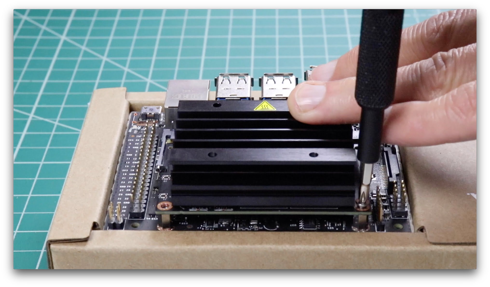
Next remove the Jetson Module from the carrier board by removing the two Phillips #1 screws at the front of the module. Then release the side latches located on either side of the module. These hold the Nano SODIMM module in place. The module will pop-up. Remove the module.

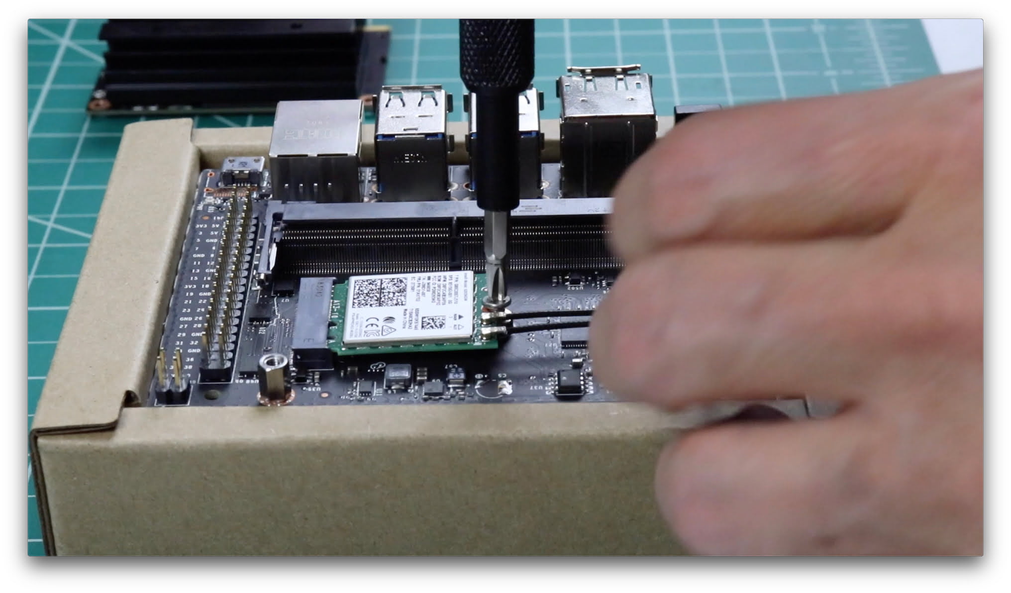
Remove the #2 Phillips screw located in the center of the board. Insert the Wifi card into the M.2 connector at a slight angle, and seat the card. Then install the #2 retaining screw. Route the wires from the antennas appropriately. You can use Kapton tape (1/8″ to 1/4″) to help secure them:

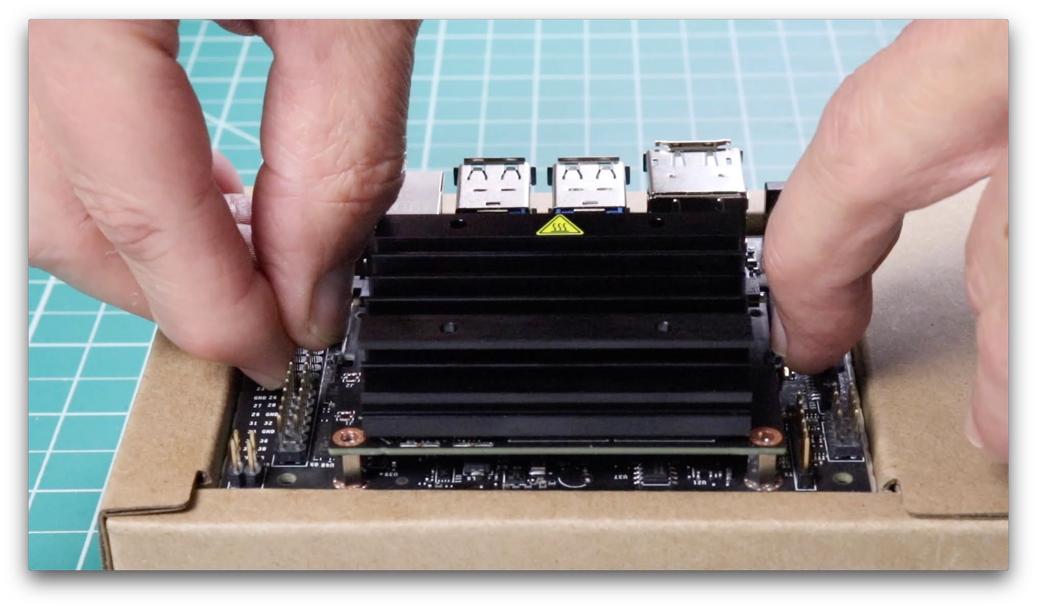
Replace the Jetson Nano SODIMM module. Angle the card up slightly in relationship to the connector, and insert the card. Make sure that it seats correctly. Then press down on the card until retained by the latches. Then replace the #1 screws to secure the board. Installation complete!

You are now ready to use the Jetson. Plug everything in, and follow the usual wireless network selection process. See the video if you need more details.

In the video, we played around with a Sony Playstation PS4 controller. If you’re a maker, that’s a straightforward way to get easy input from buttons and variable input from the joysticks and triggers.

Conclusion

There’s a couple of ways to think about having Wifi access. One way is to think that it could have been added to the board inexpensively, and should be standard. While that’s certainly a valid view, not integrating the wireless and leaving a separate slot for expansion is a great alternative for people who want more flexibility in their choices.

Folks have different needs, some may want cell connectivity, for example. Plus, it makes the whole validation process a lot easier not having to include the radio (each country usually has their own standards), so that the Jetson Nano can roll out worldwide at a quicker rate.

The post Jetson Nano + Intel Wifi and Bluetooth appeared first on JetsonHacks.

Jetson Nano – Use More Power!

$
0
0

You need to get all the power out of your Jetson Nano Developer Kit. Looky here:

Background

There are three ways to get power in to the NVIDIA Jetson Nano Developer Kit. The simplest is to supply 2 Amps at 5 Volt to the micro-USB connector. The hardest is to supply power through the GPIO Header. The GPIO Header has two 5V pins, each can accept up to 3 Amps. This gives 6 Amps total.

We cover the third possibility here. Supply 4 Amps at 5 Volts through the Barrel Jack connector. That’s what the cool kids do, you should too!

Why not Micro USB

There are times when you’ll may want to run your Jetson Nano through micro-USB. It’s pretty convenient; all you need is a cable and phone charger wall wart that you have laying around (make sure it’s 2 Amp). But here’s the thing …

The Jetson Nano module runs in 10 Watt mode by default. Quick math tells us that is 2A @ 5V. Sounds like everything’s good, right? Nope. That’s only for the Nano module, not the full board and attached peripherals. By the time you add on a keyboard, mouse, cameras and all the good stuffs, you’re over that. The Nano doesn’t like that so it turns itself off, similar to a circuit breaker when you draw too much current in your house.

Note: When running from the micro-USB connector, you should probably be running in 5V mode. See the ‘Notes’ section below on how to do that if you must.

What to Do?

Use the Barrel Jack Connector! You can supply 4A @ 5V, which should be plenty for most projects.

Installation

You will need two things. First, a power supply. In the video, we use a Adafruit 4A @ 5V power supply. The connector on the power supply is 5.5mm outer diameter (OD) x 2.1 mm inner diameter (ID) x 9.5mm length. This can be pretty easily confused with a 5.5mm OD x 2.5 mm ID, so make sure you get the right one.

You will also need a jumper pin. These are the standard 2.54mm hobbyist style. Also, you will also need an extra jumper pin if you plan to flash the Nano with NVIDIA SDK Manager, so at least get a couple. In the video, we use a bag of color jumpers. You may be able to get along with a bunch of black ones if you are soul less. SparkFun sells onesies if you just want to buy a couple.

You need to place one of the jumpers on J48. J48 is located between the Barrel Jack connector and the Camera connector. This jumper tells the Nano to use the Barrel Jack instead of the micro-USB port. Then plug the power supply into the Barrel Jack, and the Nano boots. No fuss, no muss.

Install J48 Jumper
Install J48 Jumper

Pro Tip

In the video, we label the power supply transformer, and add color electrical tape to the barrel jack to distinguish them from other, similar devices. You’ll find this is pretty common when you get out to places where people make their living do such things.

The reason people do this is that even though all the transformers and power supplies look similar (in fact the jacks can be the same size), the transformers may supply different voltages. For example, both the Jetson Nano and the Jetson TX2 share the same connector size, but the Jetson TX2 uses 19 volts, and the Nano uses only 5 volts. If you plug the TX2 power supply into the Nano, all the magic smoke will leave and you will be sad. And people ask why I have a fire extinguisher in the videos!

Notes

The Jetson has two power profiles, called modes. Mode 0 is 10W, Mode 1 is 5W. To set the mode to 5 Watt mode:

$ sudo nvpmodel 1

To set it back to 10 Watt mode:

$ sudo nvpmodel 0

The default image on the Jetson Nano is in 10 Watt mode. There’s another utility name jetson_clocks with which you may want to come familiar. Here’s a video which explains power management, modes and jetson_clocks in slightly more detail. Looky here:

The post Jetson Nano – Use More Power! appeared first on JetsonHacks.
Jetson Nano – Use More Memory!

$
0
0

The NVIDIA Jetson Nano Developer Kit has 4 GB of main memory. This may not enough memory for running many of the large deep learning models, or compiling very large programs. Let’s fix that! We are going to install a swapfile. Looky here:

Background

There may be times when you are running your Jetson Nano when the screen suddenly freezes. You may have a lot of browser tabs open, or be running multiple YouTube videos, or other memory hungry applications.

If you are a developer, or are loading large trained models, sometimes in the Terminal console you will see your program aborted with the simple word ‘Killed’. More than likely, this is because you ran out of memory.

The Jetson Nano has 4 GB of RAM. Sometimes this is not enough for big jobs. Fear not! There is a feature in the Linux kernel, called a swapfile, which implements paged memory. You can read all about swapfiles here: Ubuntu Swap FAQ.

Installation

On the JetsonHacksNano account on Github, there is a repository named installSwapFile. Clone the repository, and then switch over to the repository directory:

$ https://github.com/JetsonHacksNano/installSwapfile
$ cd installSwapfile

Here’s the usage instruction:

usage: installSwapFile [[[-d directory ] [-s size] -a] | [-h]]

All of the arguments are optional. The default is for a 6GB swapfile to be created in the directory /mnt. The -a flag indicates whether the swapfile should be automatically be loaded on boot. If the swapfile is to be loaded at boot time, make sure that the location is mounted when the machine boots.

You can run the default:

$ ./installSwapfile

and a 6 GB swapfile will be installed at /mnt/swapfile

Note: You will need to have enough extra room on your device to install the swapfile.

For the 4 GB Jetson Nano, the 6 GB swapfile is what Ubuntu recommends assuming that you are using hibernation. Otherwise 2 GB should do.

In the video, the swap file is auto mounted when the machine boots. This is great for development, but afterwards you may want to disable that feature. To do so:

$ sudo gedit /etc/fstab

and comment out the line that does the ‘swapon’. Make sure to save the file, reboot and check to make sure that swap is off. 

Also, you may want to be a little more hard core about your swap area. You can set aside a ‘swap partition’ and use that instead of a swap file. This approach may be faster because the swap area is set aside contiguously. This route is similar to setting up a swap file, but is beyond the scope of this article.

Conclusion

This is a pretty simple way to make your Jetson Nano much more responsive, and provide more memory for those large builds and deep learning models.

The post Jetson Nano – Use More Memory! appeared first on JetsonHacks.
Jetson Nano – Automount Drive

$
0
0

There are times when you need to have your external drives mounted when the Jetson Nano boots. Let’s go over it! Looky here:

Introduction

The Ubuntu documentation has a good summary of storage devices, volumes and partitions. Money quote:

The word volume is used to describe a storage device, like a hard disk. It can also refer to a part of the storage on that device, because you can split the storage up into chunks. The computer makes this storage accessible via your file system in a process referred to as mounting. Mounted volumes may be hard drives, USB drives, DVD-RWs, SD cards, and other media. If a volume is currently mounted, you can read (and possibly write) files on it.

Often, a mounted volume is called a partition, though they are not necessarily the same thing. A “partition” refers to a physical area of storage on a single disk drive. Once a partition has been mounted, it can be referred to as a volume because you can access the files on it. You can think of volumes as the labeled, accessible “storefronts” to the functional “back rooms” of partitions and drives.

Ubuntu Documentation

The system does not automatically mount all partitions. For example if you leave a USB drive in and reboot the system, the flash drive does not automatically mount. If you need the drive mounted, let’s say you are using it for a swapfile, you will need to tell the system to automatically mount the drive.

Here’s some documentation about Automounting Partitions Automatically. The discussion is fairly rich in dealing with different system level parameters. In our case, we will be using per-user mounting to automount a drive.

Installation

In a previous article on setting up a swapfile on the Jetson Nano, we state that:

If the swapfile is to be loaded at boot time, make sure that the location is mounted when the machine boots.

However, we didn’t really go over how to do that with an external drive, such as a USB drive. In the video, we automount a Samsung 500GB Solid State Disk (SSD), though you can use a smaller SSD, or a USB Hard Disk Drive (HDD). This works with thumb drives too.

The configuration file /etc/fstab contains the necessary information to automate the process of mounting partitions. In a nutshell, mounting is the process where a raw (physical) partition is prepared for access and assigned a location on the file system tree (or mount point).

Introduction to fstab

There is a convenience script in the JetsonHacksNano account on Github in the installSwapfile repository. This is the same repository we use in the previous article for installing the swapfile. Note: The repository has been updated to include the autoMount convenience script. You will need to update the repository if it is already installed.

First, clone the repository:

$ git clone https://github.com/JetsonHacksNano/installSwapfile

and then switch to the repositories directory:

$ cd installSwapfile

You are then ready to prepare the fstab entry. You will need to know the volume label which you wish to mount.

$ ./autoMount.sh -l <volume label>

The script will form the fstab entry, and ask if you want to include it in /etc/fstab.

This is an area where there are many options, the script simply uses the most common options for a removable drive. You may want to modify the fstab entry or script to suit your needs.

Conclusion

Automounting is a useful tool when you need to have a drive available right after boot. Hopefully this will guide you (or provide enough information to act as a jumping off point) to set up this feature.

Notes

  • Tested on Jetson Nano, L4T 32.1.0

The post Jetson Nano – Automount Drive appeared first on JetsonHacks.


Jetson Nano – Serial Console

$
0
0

A Serial Console is a useful tool for embedded development, remote access, and those times when the development kit has issues that you need to observe. Looky here:

Background

The story of serial data transfer over wires goes back almost a hundred years. I’ve heard stories that Ferdinand Magellan first discovered a serial cable on his journeys, but lost it to a tangle in the battle of Mactan in 1521. Apparently it was later rediscovered in America where teletypewriters used serial communication technology over telegraph wires, the first patents around stop/start method of synchronization over wires being granted around 1916. 

Serial communication in the computer industry is ubiquitous, in this case we are going to connect a PC up to the Jetson Nano Developer Kit via the UART on J44. This UART is the serial console on the Jetson Nano which allows direct access to the serial and debug console. Quite a handy thing to have when the going gets hardcore.

In addition to providing the typical console, the serial console is useful in many other situations. This includes the ability to choose menu entries for different boot Images (Linux kernel images), as well accessing a Nano that does not have a keyboard, mouse, networking or display.

Installation

Because the Nano communicates over a basic serial cable, almost any computer with serial terminal software can communicate with the Jetson. There are a wide range and variety of software terminal emulators out there. In this video, a laptop running Ubuntu and the program Minicom is shown. Other platforms and software programs can be used including Windows and Macintosh boxen.

The Jetson Nano J44 header uses TTL logic. While there are various ways to interface with it, we chose to convert the signal to USB. In the video, we use an Adafruit USB to TTL Serial Cable – Debug / Console Cable [954] available from Amazon.

There are a wide variety of offerings for these types of cable. The products fall in two camps. The first camp uses FTDI chips for TTL to USB conversion, the second camp uses PL2303HX chips. The Adafruit cable is in the latter camp. One thing to keep in mind is that a driver for the appropriate chip may be required for the cable to work correctly with your particular operating system. The driver for the PL2303HX was already installed on the machine being used in the demonstration.

Wiring

The wiring is straightforward. Make sure that the Nano is not powered and wire:

Jetson Nano J44 Pin 2 (TXD) → Cable RXD (White Wire)
Jetson Nano J44 Pin 3 (RXD) → Cable TXD (Green Wire)
Jetson Nano J44 Pin 6 (GND) → Cable GND (Black Wire)

The Jetson Nano J44 pins are also silkscreened on the underside of the board. Here’s what it should look like:

Software

Before you can connect with a serial terminal application on the other computer, you will need to determine the port to which the Jetson Nano connects. This is dependent on the computer you are using.

In the video on the Ubuntu PC, we open a new Terminal and:

$ dmesg −−follow

Next, plug in the Serial Cable. You will see a driver assign the cable a port number. In the video, the cable is ttyUSB0.

In the video, we use the Minicom application. Other programs/platforms should be similar. We’ll cover the video walkthrough. Install Minicom:

$ sudo apt-get install minicom

To start Minicom:

$ sudo minicom

The ‘sudo’ is used because of serial port permissions. You’re then ready to configure the Settings to communicate with the Jetson Nano.

Settings

An important part of serial communication is settings that are used to communicate between the devices. Rather than go through a lengthy discussion of each setting and it’s meaning, let’s distill it into the settings themselves.

First set the device, in the video the device was ‘/dev/ttyUSB0‘.

Connection speed is 115200, with 8 bits, no parity, and 1 stop bit (115200 8N1). For these three wire cables, the correct setting is software control, no hardware control. If you choose a 5 wire setup with RTS and CTS lines, then select hardware control, and no software control.

In Minicom, Ctrl A Z brings up the main menu. Select the ‘cOnfigure Minicom’ menu item, enter the settings, and make sure that you save the configuration as described in the video. After that task is complete, exit Minicom and restart to have the settings take effect.

$ sudo minicom

Now power on the Jetson Nano, at which point you will see the kernel log starting to scroll on the Minicom window on the host.

There are a wide variety of ways to interact with the Nano through the serial console, one of the more useful tips is to interrupt the startup process with a keystroke to be able to interact with the bootloader.

You can also choose different kernels during this process when they are present. If you do not interrupt the process with a keystroke, the Nano will boot and you will be at a Terminal prompt.

Conclusion

The Serial Console is a useful tool to help debug the startup sequence, load different Linux kernels, or simply act as a headless console. All it takes is one wire, and you can talk to your Jetson Nano!


The post Jetson Nano – Serial Console appeared first on JetsonHacks.

Jetson Nano – Run on USB Drive

$
0
0

Using a USB Drive as the root file system on a Jetson Nano Developer Kit provides many advantages, including faster disk access and more storage. Looky here:

Background

For external storage, the Jetson Nano uses a Micro SD Card. The SD card holds the operating system, applications and any data in use. In the overall scheme of things, this device provides relatively slow access. Also, even though Micro SD cards are much better now than they have been in the past, the cards have a reputation of low reliability in long term or heavy use.

Most desktop/laptop computers use a different type of external storage, such as a Hard Disk Drive (HDD) or Solid Sstate Disk (SSD). Typically these are built into the computer, though you can add an external one also.

In fact, we can add one of those types of drives to the Jetson Nano through the USB 3.0 port! We will cover setting up our USB drive so that it can act as the “root file system” for the Nano. Conceptually, this means that the Nano is running off of the USB drive.

Typically most larger computers boot directly to the disk drive. However, this is not possible using the current configuration boot loader on the Jetson Nano. The boot loader understands USB 2.0, the Nano speaks USB 3.0.

Remember that the term ‘boot’ is shorthand for the slang term ‘bootstrapping’, that is, pulling ones self up by their own boot straps. The Jetson uses a two step boot process. The basic idea is that the boot loader loads a memory image with minimal support for key attached peripherals, and then loads over itself with the Linux kernel specified. It’s really clever and quite tricky.

The solution here is to tell the boot loader to use the USB drive as the new root file system. But in order to be able to do that, we have to embed the USB 3 driver directly into the Linux kernel itself (the kernel file is called ‘Image’). Therefore we end up building a new kernel to include the USB 3 driver, and replacing the old one

Installation

Note: Before we get started, a major shout out goes out to Syonyk’s Project Blog for deciphering how to place the Tegra USB firmware in to the kernel. A very nice write up is available there. Thank you!

USB Drives

In the video, we took a look at the following drives:

  • Samsung T5 500 GB USB SSD: https://amzn.to/2PtE7bK
  • Samsung 860 Pro 256GB SATA III: https://amzn.to/2UEWQCb
  • SATA SSD to USB cable: https://amzn.to/2UEB1md
  • Western Digital 2TB External Hard Drive: https://amzn.to/2GH50WY

Install

You should do this on a freshly flashed Micro SD card. On the JetsonHacksNano account on Github, there is a repository named rootOnUSB. Clone the repository, and then switch to the repositories directory:

$ git clone https://github.com/JetsonHacksNano/rootOnUSB

$ cd rootOnUSB

You are now ready to build the kernel:

$ ./buildKernel.sh

It takes ~ 45 minutes to download and build the kernel. You should reboot the machine to make sure the Image build is correct. You are now ready to copy the root file system from the Micro SD card to the USB drive.

First, prepare a USB drive by formatting it Ext4 with at least one partition. In the video, we assign a volume label. If you need instructions for formatting, check out the video where we do so using the ‘Disks’ application.

Make sure that the USB drive is mounted (you can open a file browser on it to make sure it is mounted). To copy the root:

$ ./copyRootToUSB.sh -v <Volume Label>

OR

$ ./copyRootToUSB.sh -d <Directory Path>

An example of the first and the latter:

$ ./copyRootToUSB.sh -v NanoSSD500

OR

$ ./copyRootToUSB.sh -d /media/jetsonhacks/NanoSSD500

It will take several minutes to copy over all the files.

The final step is to modify /boot/extlinux/extlinux.conf to tell the Nano to switch over to the USB drive. Make a backup of the file, and then duplicate the primary entry. Rename the label of the original entry, and then set the primary entry to point to the USB device. Typically the USB drive will be /dev/sda1 (1 is the partition). The important line needs to be:

APPEND ${cbootargs} rootfstype=ext4 root=/dev/sda1 rw rootwait

There is a file named sample-extlinux.conf which is a sample of the a modified extlinux.conf file might look like. Notice that the label on the second entry is emmc, which represents the Micro SD device address. If you use the serial console for debugging, you will see two entries that you can boot, “primary” and “emmc”. The first is the USB drive, the second the Micro SD card. This can come in handy if the machine decides not to boot after you make your changes.

Benchmarks

If you use the Micro SD card, you typically get average read rates ~ 87 MB/s and access times of ~ 0.52 msec. With a SSD, you get average read rates of ~367 MB/s and access times of 0.29 msec. About a 4X speedup! A HDD drive performs about the same as the Micro SSD, but tends to be much more reliable over time.

Notes

  • Even though the Jetson Nano has 4 USB 3.0 connectors, they all go through one USB hub. Therefore, you end up sharing the USB bandwidth with all the other USB peripherals. Bandwidth can fill up quick!
  • If you use swap memory on a SSD best practice is to use a swap file, not a swap partition. The advantage over a swap partition is that the swap file will move around the disk as it is written and deleted. That way the wear leveling algorithms can help manage the loads. A partition is always in the same place.
  • Tested on Jetson Nano, L4T 32.0.1 [JetPack 4.2]

The post Jetson Nano – Run on USB Drive appeared first on JetsonHacks.

Jetson Nano – RealSense Tracking Camera

$
0
0

The Intel RealSense T265 Tracking Camera solves a fundamental problem in interfacing with the real world by helpfully answering “Where am I?” Looky here:

Background

One of the most important tasks in interfacing with the real world from a computer is to calculate your position in relationship to a map of the surrounding environment. When you do this dynamically, this is known as Simultaneous Localization And Mapping, or SLAM.

If you’ve been around the mobile robotics world at all (rovers, drones, cars), you probably have heard of this term. There are other applications too, such as Augmented Reality (AR) where a computing system must place the user precisely in the surrounding environment. Suffice it to say, it’s a foundational problem.

SLAM is a computational problem. How does a device construct or update a map of an unknown environment while simultaneously keeping track of its own location within that environment? People do this naturally in small places such as a house. At a larger scale, people have been clever enough to use visual navigational aids, such as the stars, to help build their maps.

This  V-SLAM solution does something very similar. Two fisheye cameras combine with the information from an  Inertial  Measurement  Unit (IMU) to navigate using visual features to track its way around even unknown environments with accuracy. 

Let’s just say that this is a non-trivial problem. If you have tried to implement this yourself, you know that it can be expensive and time consuming. The Intel RealSense T265 Tracking Camera provides precise and robust tracking that has been extensively tested in a variety of conditions and environments.

The T265 is a self-contained tracking system that plugs into a USB port. Install the librealsense SDK, and you can start streaming pose data right away.

Tech Stuffs

Here’s some tech specs:

Cameras

  • OV9282
  • Global Shutter, Fisheye Field of View = 163 degrees
  • Fixed Focus, Infrared Cut Filter
  • 848 x 800 resolution
  • 30 frames per second

Inertial Measurement Unit (IMU)

  • 6 Degrees of Freedom (6 DoF)
  • Accelerometer 
  • Gyroscope

Visual Processing Unit (VPU)

  • Movidius MA215x ASIC (Application Specific Integrated Circuit)

The Power Requirement is 300 mA at 5V (!!!). The package is 108mm Wide x 24.5mm High x 12.50mm Deep. The camera weighs 60 grams.

Installation

To interface with the camera,  Intel provides the open source library librealsense. On the JetsonHacksNano account on Github, there is a repository named installLibrealsense. The repository contains convenience scripts to install librealsense.

In order to use the install script, you will either need to create a swapfile to ease an out of memory issue, or modify the install script to run less jobs during the make process. In the video, we chose the swapfile route. To install the swapfile:

$ git clone https://github.com/jetsonhacksnano/installSwapfile
$ cd installSwapfile
$ ./installSwapfile.sh
$ cd ..

You’re now ready to install librealsense.

$ git clone https://github.com/jetsonhacksnano/installLibrealsense
$ cd installLibrealsense
$ ./installLibrealsense.sh

While the installLibrealsense.sh script has the option to compile the librealsense with CUDA support, we do not select that option. If you are using the T265 alone, there is no advantage in using CUDA, as the librealsense CUDA routines only convert images from the RealSense Depth cameras (D415, D435 and so on).

The location of librealsense SDK products:

  • The library is installed in /usr/local/lib
  • The header files are in /usr/local/include
  • The demos and tools are located in /usr/local/bin

Go to the demos and tools directory, and checkout the realsense-viewer application and all of the different demonstrations!

Conclusion

The Intel RealSense T265 is a powerful tool for use in robotics and augmented/virtual reality. Well worth checking out!

Notes

  • Tested on Jetson Nano L4T 32.1.0
  • If you have a mobile robot, you can send wheel odometry to the RealSense T265 through the librealsense SDK for better accuracy. The details are still being worked out.

The post Jetson Nano – RealSense Tracking Camera appeared first on JetsonHacks.

Jetson Nano – RealSense Depth Camera

$
0
0

Getting full support for the Intel RealSense Depth Camera on the NVIDIA Jetson Nano Developer Kit is simplified by using a couple of installation scripts. Looky here:

Introduction

In an earlier article, we installed an Intel RealSense Tracking Camera on the Jetson Nano along with the librealsense SDK. We’ve have used the RealSense D400 cameras a lot on the other Jetsons, now it’s time to put them to work on the Jetson Nano.

For best performance and support of the RealSense Depth Camera features, Intel recommends modifying the Linux kernel and modules.

To remind you of the different cameras available, here’s a couple of the more popular models which points out their features:

Intel® RealSenseTM Depth Camera D415

  • Intel® RealSenseTM Vision Processor D4
  • Up to 1280×720 active stereo depth resolution
  • Up to 1920×1080 RGB resolution
  • Depth Diagonal Field of View over 70°
  • Dual rolling shutter sensors for up to 90 FPS depth streaming
  • Range 0.3m to over 10m (Varies with lighting conditions)

Intel® RealSenseTM Depth Camera D435/D435i 

  • Intel® RealSenseTM Vision Processor D4
  • Up to 1280×720 active stereo depth resolution
  • Up to 1920×1080 RGB resolution
  •  Depth Diagonal Field of View over 90°
  • Dual global shutter sensors for up to 90 FPS depth streaming
  • Range 0.2m to over 10m (Varies with lighting conditions)
  • Intel® RealSenseTM Depth Camera D435i includes Inertial Measurement Unit (IMU) for 6 degrees of freedom (6DoF) data

For robotics applications, the D435 is popular due to its global shutter and wide field of view.

Software Installation

To interface with the camera,  Intel provides the open source library librealsense. On the JetsonHacksNano account on Github, there is a repository named installLibrealsense. The repository contains convenience scripts to install librealsense.

In order to use the install script, you will either need to create a swapfile to ease an out of memory issue, or modify the install script to run less jobs during the make process. In the video, we chose the swapfile route. To install the swapfile:

$ git clone https://github.com/jetsonhacksnano/installSwapfile
$ cd installSwapfile
$ ./installSwapfile.sh
$ cd ..

You’re now ready to install librealsense.

$ git clone https://github.com/jetsonhacksnano/installLibrealsense
$ cd installLibrealsense
$ ./installLibrealsense.sh

While the installLibrealsense.sh script has the option to compile the librealsense with CUDA support. If you want to add CUDA support to the librealsense SDK, add a -c switch to the shell script:


$ ./installLibrealsense.sh -c

The location of librealsense SDK products after installation:

  • The library is installed in /usr/local/lib
  • The header files are in /usr/local/include
  • The demos and tools are located in /usr/local/bin

Kernel and Modules

For the RealSense Depth Cameras, you will find that performance is much better if you apply the patches to the kernel models. Note: If you have a D435i, the camera will not be detected without the patches.

This video covers the differences between only installing librealsense versus librealsense plus the kernel modifications. Looky here:

To install the kernel and module patches, build them, and then install first switch to the installLibrealsense directory then:

You’re now ready to install librealsense.


$ ./patchUbuntu.sh

This will start the patch, build and install process. On a micro SD card this will take ~ one hour, 20 minutes. Note: If you compile the kernel and modules on a USB SSD, remember to copy the new Image to the /boot directory of the SD card which you boot from.

Demos

Go to the demos and tools directory in /usr/local/bin, and checkout the realsense-viewer application and all of the different demonstrations! There are a wide variety of code samples for different uses in the librealsense SDK. When you go to program against the SDK, you’ll benefit from having a good catalog with which to work.

The post Jetson Nano – RealSense Depth Camera appeared first on JetsonHacks.

NVIDIA SDK Manager for Jetson – JetPack 4.2

$
0
0

The NVIDIA SDK Manager installs the operating system, libraries and SDKs on the Jetson Developer Kits. Looky here:

Background

When NVIDIA introduces a new Jetson model, they usually come out with a new revision of JetPack to support it. In this case it is the Jetson Nano Developer Kit. However with the new JetPack 4.2, NVIDIA is also introducing the SDK Manager.

The SDK Manager is a completely new, much improved installer which runs under Ubuntu 16.04 or 18.04 on a PC. JetPack now refers to the collection of OS, libraries and tools which run on the Jetson platform.

Note: If you have a Jetson Nano and simply are trying to create a SD card, follow the procedure to download a disk image and flash the SD card directly.

JetPack Information

The SDK Manager may be used to install the development tools on a Jetson Development Kit, either a Jetson AGX Xavier, TX2, TX2i, or Nano. You can read more information on the JetPack web page. There’s a list of all of the System Requirements, as well as the different tools that can be installed.

Note

In addition to a Jetson, you will need another desktop or laptop computer with an Intel or AMD x86 processor. These types of machines are commonly called a PC for Personal Computer. This computer is referred to as the host for the flashing process. JetPack is an x86 binary and will not run on an ARM based machine like the Jetson. In the video, a Dell laptop is being used as the host.

Installation

For the most part, installation pretty easy. From an Ubuntu 16.04 PC or 18.04 64 bit host computer, you simply download the JetPack software from the NVIDIA web link above (you’ll have to sign in with your developer account to download JetPack) and follow the instructions in the setup guide.

The NVIDIA instructions are quite wonderful now. You should not have any issues following them.

The set of tools that you can install is flexible. You have the option to install a cross compiler on the host for building your Jetson programs on your PC.

Installation from the demo host computer to the Jetson took about an hour fifteen all together, including all the downloads on a 30 MBs Internet link, flashing the Jetson.

One thing I did notice in the setup, if ‘Automatic’ is chosen to set the Jetson into recovery mode and the Jetson has a version 3.X version running, then there may be issues like the Jetson doesn’t go into force recovery mode.

In the video, we set the Jetson TX2 into force recovery mode manually. Note: You do not need to have the Jetson connected to a network for the install, only the USB connection to the host computer using the micro USB connector. This is different from previous versions of the JetPack installer.

A nice new addition is the ability to download all of the images and supporting libraries, and then flash the Jetson offline.

Note: Some of the virtual machines just won’t work with JetPack.

Note: On the Jetson Nano, the procedure to enter recovery mode is different. Refer to the installation manual for details.

Tools Available

Here are some of the JetPack release highlights for the version 4.2:

  • Linux for Tegra (L4T) 32.1.0
  • LTS Kernel 4.9
  • TensorRT
  • cuDNN
  • VisionWorks
  • CUDA 10.0
  • Multimedia API
  • OpenCV

Developer Tools

  • Tegra Graphics Debugger
  • Tegra System Profiler 
  • PerfKit 

Samples

Here’s how to install some of the JetPack 4.2 samples. Looky here:

Do I have to have an Ubuntu PC?

The short answer is yes. You may be able to use a VM, but it is not officially supported. Here’s what NVIDIA wrote in the Jetson Forum:

The flashing must be performed from within 64-bit Linux on an x86-based machine. Running an Ubuntu x86_64 image is highly-recommended for the flashing procedure. If you don’t already have a Linux desktop, and are trying to avoid setting up dual-boot, you can first try running Ubuntu from within a virtual machine. Although convenient, flashing from VM is technically unsupported — warning in advance that while flashing from within VM, you may encounter issues such as the flashing not completing or freezing during transfer. Chances will be improved if you remove any USB hubs or long cables in between your Jetson and the host machine.

The next logical step would be to boot your desktop/laptop machine off Ubuntu LiveCD or USB stick (using unetbootin tool or similar). 

Finally, if you have an extra HDD partition, you can install Ubuntu as dual-boot alongside Windows. Flashing natively from within Ubuntu is the supported and recommended method for flashing successfully. It may be wise to just start in on dual-boot from the get-go, otherwise you may end up wasting more time trying to get the other (potentially more convenient, but unsupported) methods to work.

If you encounter issues, please ask questions on the Jetson & Embedded Systems development forums.

Conclusion

The first time through, setting up the system and flashing the Jetson can take around a little more than an hour or so depending on your download speeds and the speed of your PC. In the video, a simple cable modem 30MBs was used for downloading. Downloading all of the components only happens the first time you do an installation, subsequent installations check for updates and if none are available then simply flash the Jetson, saving a lot of time.

The post NVIDIA SDK Manager for Jetson – JetPack 4.2 appeared first on JetsonHacks.

Viewing all 339 articles
Browse latest View live